Table of Contents >> Show >> Hide
- What I2C Is (and Why Hackers Love It)
- Meet the Two Wires: SDA and SCL
- How an I2C Conversation Works
- Speeds, Modes, and Why Your Wires Have Opinions
- Electrical Reality Check: Pull-Ups, Capacitance, and Level Shifting
- Multiple Devices on One Bus: Arbitration and Clock Stretching
- SMBus vs I2C: Close Cousins (Not Identical Twins)
- Hacker Toolkit: Observe, Debug, and Prototype
- Common Failure Modes (and Fast Fixes)
- Security Notes: What I2C Can and Can’t Protect
- A Quick Note on I3C (Because Someone Will Bring It Up)
- Conclusion
- Field Notes: Practical “I2C Experiences” That People Run Into (and Learn From)
- 1) The “It’s Powered, So It Should Work” illusion
- 2) The address that’s correct… in a different universe
- 3) The “two boards, two pull-ups, one bus, infinite confidence” trap
- 4) When 400 kHz turns into performance art
- 5) The “stuck bus” mystery that’s actually a single confused slave
- 6) Clock stretching: the polite pause that some controllers ignore
- 7) Register reads that require a repeated START (and get cranky without it)
- 8) The “my logic analyzer says it’s fine” momentuntil you zoom in
- 9) Emulating a missing part to keep a device alive
- 10) The final boss: blaming software when it’s actually grounding
I2C (pronounced “eye-squared-see” or “I-two-C”) is the quiet little workhorse that helps chips gossip with each other inside
everything from thermostats to game controllers. If you like taking gadgets apart, swapping sensors, or poking at mystery boards
with a logic analyzer like a digital detective, I2C will show up constantlyusually right when you weren’t planning on learning it.
This guide breaks I2C down in plain English, with just enough electrical reality to keep your signals from looking like sad spaghetti.
You’ll learn how the bus talks, what the bytes mean, why pull-up resistors are non-negotiable, and how to debug the classic “it’s not
working but I swear it should” moment.
What I2C Is (and Why Hackers Love It)
I2C is a short-distance, on-a-board serial communication bus designed for chips that live close together. It uses two wires:
one for data (SDA) and one for clock (SCL). Multiple devices can share the same two wires, which is why it’s common to see
a microcontroller chatting with a temperature sensor, an EEPROM, and a display driver all on the same bus.
For hardware tinkerers, I2C is attractive because it’s easy to identify, widely supported (Linux, Arduino, Raspberry Pi, microcontrollers),
and often exposes interesting configuration registers or stored data. It’s also usually unencrypted, which is convenient for debugging
and a good reminder to design security intentionally instead of hoping the wires “keep secrets.”
Meet the Two Wires: SDA and SCL
Open-drain: the “nobody drives high” rule
The most important I2C concept isn’t softwareit’s electrical. SDA and SCL are typically open-drain (or open-collector).
That means devices can pull the line low, but they don’t actively drive it high. Instead, the line is pulled high by
pull-up resistors to a supply voltage.
Why do it this way? Because it lets multiple devices share the same line safely. If one device pulls low while another “wants” high,
low winswithout a direct short between two push-pull outputs. Think of it like a group chat where anyone can shout “NO!” (pull low),
but “YES!” (high) only happens when nobody is shouting.
Pull-ups are not “optional accessories”
No pull-ups means the bus floats, and floating digital lines are basically fortune-tellers: sometimes high, sometimes low, always wrong.
Most boards use pull-ups in the ballpark of 1.8 kΩ to 10 kΩ, with 4.7 kΩ being a common “works in many cases”
value. The best value depends on voltage, bus capacitance, number of devices, and speed.
How an I2C Conversation Works
I2C is master-driven. The master generates the clock on SCL and initiates transactions. The slave responds
when addressed. Some systems support multiple masters, but most everyday setups are “one master, many slaves.”
START and STOP: the bookends
An I2C transaction begins with a START condition: SDA transitions from high to low while SCL is high.
It ends with a STOP condition: SDA transitions from low to high while SCL is high.
Those edge cases matter because data bits are normally only supposed to change while SCL is low.
Address byte: “who am I talking to?”
After START, the master sends an address plus a read/write bit. Most devices use 7-bit addresses.
That means the address takes 7 bits, and the 8th bit indicates direction:
- Write: master sends data to the slave
- Read: master reads data from the slave
The classic confusion: some datasheets list the 7-bit address (like 0x3C), while some libraries want the 7-bit form and handle the R/W bit
internally. Other tools show the “8-bit address” (like 0x78/0x79) which is just the 7-bit address shifted left by one, plus the R/W bit.
If your device “doesn’t exist,” this is a top-3 suspect.
ACK/NACK: the tiny handshake that keeps you honest
Data is transferred in 8-bit bytes. After each byte, the receiver sends an ACK bit by pulling SDA low on the ninth clock pulse.
If it leaves SDA high, that’s a NACK. ACK usually means “got it, continue,” while NACK can mean “no device,” “wrong time,”
or “I’m done” (especially at the end of reads).
A practical example: reading a register from a sensor
Many I2C sensors use a register map. A common read flow looks like this:
- START
- Send device address + Write
- Send register address (the “pointer”)
- Repeated START (without releasing the bus)
- Send device address + Read
- Read one or more data bytes (master ACKs each byte it wants to continue)
- Master NACKs the final byte (meaning “I’m done reading”)
- STOP
That “repeated START” is a big deal: it keeps the transaction atomic, so another master (in multi-master systems) can’t cut in line.
Even with one master, repeated START is standard practice for register reads.
Speeds, Modes, and Why Your Wires Have Opinions
I2C supports multiple speed grades. The common ones you’ll see:
- Standard-mode: 100 kHz
- Fast-mode: 400 kHz
- Fast-mode Plus: 1 MHz
- High-speed mode: 3.4 MHz (more specialized)
Higher speed means stricter rise-time requirements. Remember: lines rise through pull-up resistors, not active drivers, so the “high” edge
is shaped by the resistor and the bus capacitance. If your SDA rise looks like a slow hill instead of a crisp edge, your bus may work at 100 kHz
and fail miserably at 400 kHz.
Electrical Reality Check: Pull-Ups, Capacitance, and Level Shifting
Choosing pull-up values (the not-too-mathy version)
Bigger resistors (like 10 kΩ) pull up more gently: lower power, but slower rise times. Smaller resistors (like 2.2 kΩ) pull up harder:
faster edges, but more current when a device pulls the line low. There’s no universal “best.” The best resistor is the one that makes your bus
pass at the speed you need without cooking anything or wasting power.
Bus capacitance: the invisible “wire length tax”
Every trace, cable, and input pin adds capacitance. More capacitance makes your rising edges slower. If you run I2C off-board with long wires,
you’re basically turning a friendly two-wire protocol into a moody analog experiment. Short, tidy wiring and reasonable speed settings keep life peaceful.
Mixing voltages: level shifting without drama
I2C is often used between 3.3 V parts and 5 V parts. Because lines are open-drain, a common approach is a small MOSFET-based level shifter
(many breakout boards include one). The idea is to keep each side pulled up to its own voltage while still letting “low” propagate across the boundary.
If you connect a 3.3 V device directly to 5 V pull-ups, you may get lucky… until you don’t.
Multiple Devices on One Bus: Arbitration and Clock Stretching
Arbitration: when two masters talk at once
In multi-master I2C, arbitration prevents chaos. Because low wins on the bus, a master that tries to send a ‘1’ but sees a ‘0’ on SDA
knows another master is asserting low. The losing master backs off, and the winner continues. It’s polite, electrical conflict resolution.
(If only group projects worked this way.)
Clock stretching: “hold on, I’m thinking”
Some slaves can pause a transaction by holding SCL lowthis is called clock stretching. It lets a slower device catch up,
for example while it fetches data from an internal ADC or EEPROM. Not all I2C controllers handle clock stretching equally well; some hardware
or bit-banged implementations assume the clock always moves forward. If your bus “hangs,” clock stretching is another prime suspect.
SMBus vs I2C: Close Cousins (Not Identical Twins)
SMBus (System Management Bus) is related to I2C and often compatible at the electrical level, but it adds rules:
defined timeouts, certain required behaviors, and common command formats. Many PC-style devices (battery monitors, thermal sensors)
speak SMBus-like dialects. In practice, lots of equipment blurs the lineso you’ll see Linux tools and microcontroller libraries that can do both.
Hacker Toolkit: Observe, Debug, and Prototype
“Hacking” I2C doesn’t have to mean doing anything shady. Think of it as rapid understanding: identifying devices, reading sensor data,
verifying firmware changes, and debugging hardware without guessing. The following tools and techniques are the bread and butter of legitimate
reverse engineering and repair work on devices you own (or have permission to test).
1) Spotting I2C on a board
- Look for two traces that run together between chips
- Look for labels like SDA and SCL on test pads or connectors
- Look for pull-up resistors to a logic rail near those lines
- Search for common I2C parts: EEPROMs (24xx series), sensors, RTCs, port expanders
2) Logic analyzer: the truth serum
A logic analyzer with an I2C decoder is the fastest way to turn “mystery squiggles” into readable transactions. You’ll see addresses,
bytes, ACK/NACK, and timing. It’s also how you catch sneaky issues like repeated STARTs you didn’t know were happening, or a device that NACKs
only every third transaction because it’s busy.
3) Bus scanning: “who’s home?”
On Linux systems (including Raspberry Pi), common utilities can scan the bus for responding addresses. A scan can quickly confirm that:
(a) the bus is alive, (b) pull-ups exist, and (c) at least one device acknowledges.
Important: scanning is not perfectly harmless. Some devices don’t like being poked with random reads/writes, especially if they interpret certain
commands as “do a thing.” If you’re scanning a fragile or unknown device, use conservative tools and read datasheets when possible.
4) Injecting or emulating (with permission)
Once you can sniff I2C, you can sometimes emulate a missing sensor or replace a peripheral with a microcontroller. This is powerful for repairs,
prototyping, and understanding systemslike verifying how a controller behaves when a sensor reports extreme values (within safe, intended testing).
Common Failure Modes (and Fast Fixes)
Problem: nothing ACKs
- Check pull-ups: confirm SDA/SCL idle high
- Check voltage: are you pulling up to the right rail?
- Check address format: 7-bit vs shifted 8-bit confusion
- Check wiring: SDA/SCL swapped is a classic
- Check speed: drop to 100 kHz and see if it magically behaves
Problem: bus stuck low
If SDA is stuck low, a slave may be holding it (or you have a short). Sometimes a reset fixes it. Another common recovery technique is to toggle SCL
a number of times (often up to 9 pulses) to “clock out” a stuck byte, then issue a STOP. Many microcontroller SDKs include an I2C bus recovery routine
for this exact reason.
Problem: it works on the bench, fails in the enclosure
Congratulations, you’ve discovered capacitance, EMI, and the fact that real products are not breadboards. Shorten wiring, improve grounding,
lower bus speed, and consider stronger pull-ups (within spec) or better layout. I2C is happiest when it stays “inside the PCB neighborhood.”
Security Notes: What I2C Can and Can’t Protect
I2C was designed for convenience, not confidentiality. If someone can physically access the bus, they can often observe traffic and potentially
influence it. That’s not a reason to panic; it’s a reason to be intentional. If you need security, consider:
- Keeping sensitive secrets in dedicated secure elements
- Using cryptographic authentication at the application layer
- Designing the system so “sniffing the bus” doesn’t reveal something catastrophic
For hackers doing legitimate research, this is also why I2C is useful: it’s an honest bus. It tells you what the system is doingsometimes more than
the system designer intended.
A Quick Note on I3C (Because Someone Will Bring It Up)
I3C is a newer standard that aims to improve on I2C with higher speed, better efficiency, and features like in-band interruptswhile often sharing
physical lines and maintaining backward compatibility with many I2C devices. You don’t need I3C to understand I2C, but it’s good context:
I2C is “classic,” and the world is still building on it.
Conclusion
I2C is simple in concepttwo wires, shared busbut rich in real-world quirks. If you remember only a few things, make them these:
open-drain needs pull-ups, addresses are a frequent source of confusion, and a logic analyzer can save you hours of guessing.
Once you can read and reason about START/STOP, ACK/NACK, and register-style transactions, you can move from “I hope this works” to
“I know exactly what the bus is doing.”
And that’s the core hacker skill: replacing mystery with evidence… preferably before your coffee gets cold.
Field Notes: Practical “I2C Experiences” That People Run Into (and Learn From)
Below are the kinds of I2C moments that show up again and again in real builds, teardowns, and debug sessionsshared here as lived-in lessons
without pretending the bus is always polite.
1) The “It’s Powered, So It Should Work” illusion
People often assume a powered sensor will respond automatically. Then they scan the bus and… nothing. The punchline is usually pull-ups:
the lines never go high, so the “bus” is basically two sad wires doing interpretive dance. Once proper pull-ups are added (or confirmed on the board),
devices suddenly “exist.”
2) The address that’s correct… in a different universe
A classic: the datasheet says the address is 0x68, but your library expects 0x68 and you gave it 0xD0 (or vice versa). Or the breakout board has
an address pin tied differently than the example. The fix is boring but satisfying: confirm whether you’re using 7-bit addresses, check any address
select pins, and verify on a logic analyzer which address byte is actually on the wire.
3) The “two boards, two pull-ups, one bus, infinite confidence” trap
Breakout boards often include pull-ups. Add three breakouts and suddenly you have multiple pull-ups in parallel, effectively making the pull-up
resistance much smaller. The bus might still workbut it can increase current draw and stress devices when lines are pulled low. A common field fix
is to remove or disable extra pull-ups so the combined value lands in a sensible range.
4) When 400 kHz turns into performance art
At 100 kHz, almost everything works. At 400 kHz, weak pull-ups and long wires become a problem, and waveforms stop looking like digital signals.
People learn quickly that “faster” is only better when your rise times can keep up. Dropping speed is the fastest sanity checkand often the fastest
path to a stable product.
5) The “stuck bus” mystery that’s actually a single confused slave
Sometimes a device resets mid-transaction, or the master resets, or a cable wiggles at the wrong time. The result can be SDA held low, and suddenly
the entire bus looks dead. Many developers discover bus recovery the hard way: toggling SCL to finish a byte, then issuing a STOP. It feels like
performing an exorcism, but it’s standard practice in robust designs.
6) Clock stretching: the polite pause that some controllers ignore
A device stretches the clock because it needs time, and your master controller responds by… pretending nothing happened. That mismatch can cause hangs
or corrupted reads. The “experience” here is learning to check whether your platform supports clock stretching, and if not, choosing parts (or drivers)
that don’t rely on it.
7) Register reads that require a repeated START (and get cranky without it)
Many devices expect a repeated START between writing the register pointer and reading data. Some naive code issues a STOP instead, and a few chips
interpret that as “transaction over, pointer reset.” When you see reads returning the wrong register or repeating stale data, repeated START becomes
your new best friend.
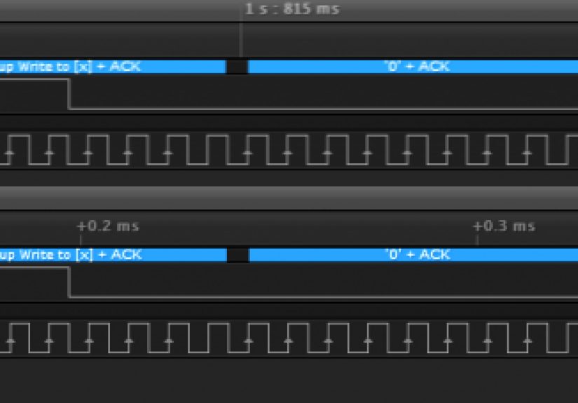
8) The “my logic analyzer says it’s fine” momentuntil you zoom in
At a glance, the transaction decodes correctly. Zoom in, and you notice slow rising edges, ringing, or a line that barely reaches a valid high
before the next clock. That’s when people appreciate that digital protocols still live in an analog world. Adjust pull-ups, reduce speed, and tidy
wiringthen the decode becomes stable instead of “mostly okay.”
9) Emulating a missing part to keep a device alive
In repairs and prototyping, it’s common to emulate a sensor or EEPROM to see how the rest of the system behaves. This teaches a powerful lesson:
many products don’t “need” the real sensor at firstthey need a believable I2C response. Used responsibly on your own hardware, emulation is a fast
way to validate theories without waiting for replacement parts.
10) The final boss: blaming software when it’s actually grounding
People can spend hours rewriting I2C drivers only to discover the real problem is a flaky ground clip or a breadboard rail that isn’t connected.
The experience here is humbling: always verify power and ground first, then confirm SDA/SCL idle high, then debug protocol. It’s not glamorous,
but it saves your weekend.