Table of Contents >> Show >> Hide
- What Is a Fluid Coupling, Anyway?
- A Short, Greasy History of Fluid Couplings
- Inside the Hydrodynamic Magic
- Fluid Coupling vs. Torque Converter: What’s the Difference?
- Where Fluid Couplings Show Up in the Real World
- Why Hackaday’s Retrotechtacular Film Still Rocks
- Why Fluid Couplings Still Matter in a Solid-State Age
- Hands-On Experiences with Fluid Couplings (Retrotechtacular Edition)
Long before everything had a microchip and a Bluetooth logo, engineers had to solve messy,
mechanical problems with… more mechanics. One of the coolest examples is the
fluid coupling – a hydrodynamic device that quietly moved power from engines
to gearboxes using nothing more than spinning metal and a bath of oil.
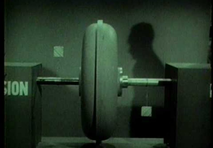
Hackaday’s “Retrotechtacular: Fluid Coupling” dusts off a 1950s Department of Defense
training film that explains this elegant bit of engineering magic in glorious black and white.
In true retro fashion, the film uses cutaway housings, swirling fluid, and a very serious
narrator to show how you can connect an engine to a transmission without a
mechanical clutch – and without shredding gear teeth every time you pull away from a stop.
In this article, we’ll ride along with that Retrotechtacular video as a jumping-off point,
then dive deeper into how fluid couplings work, where they came from, how they differ from
torque converters, and why they still show up today in big industrial machines and trains.
Think of this as your friendly, modern companion to a mid-century training reel.
What Is a Fluid Coupling, Anyway?
At its core, a fluid coupling (also called a hydraulic coupling
or fluid flywheel) is a device that transmits rotating mechanical power
from one shaft to another using a moving fluid instead of a rigid mechanical link.
It’s basically a round metal donut full of oil that acts like a clutch you can’t burn out.
The basic parts
A simple fluid coupling has four main elements:
-
Housing (shell): A sealed metal casing that holds everything together and
keeps the fluid inside while the whole assembly spins. -
Impeller (pump): The input element bolted to the engine or motor. It has
curved vanes that fling fluid outward when it spins. -
Runner (turbine): The output element connected to the load (like a gearbox
input shaft). Its vanes catch the moving fluid and begin to spin. -
Working fluid: Usually oil or automatic transmission fluid, chosen for its
viscosity, temperature behavior, and ability to resist foaming and oxidation.
That’s it. No clutch discs, no friction linings, no complicated linkages. Just two “fan wheels”
facing each other in a sealed oil bath.
How a fluid coupling transmits power
Imagine the impeller as a spoon stirring a bowl of thick soup, and the runner as another spoon
sitting in that same soup. When you stir fast enough, the second spoon starts to rotate just
from the swirling liquid. That’s basically how a fluid coupling works, only with better
metallurgy and fewer vegetables.
-
The engine spins the impeller, which throws the fluid outward by centrifugal
force. - The fluid flows in a toroidal (donut-shaped) path from the impeller into the runner’s vanes.
-
The change in direction and speed of the fluid in the runner’s vanes creates a
torque on the runner, causing it to spin. -
As the runner speeds up and approaches the impeller’s speed, the relative motion of the fluid
decreases, so the torque transfer approaches a steady, nearly locked condition.
There’s always a little slip – the output is never quite as fast as the input –
but that’s a feature, not a bug. It allows smooth starts and protects the drivetrain from shock
loads when the engine speed suddenly changes.
A Short, Greasy History of Fluid Couplings
The fluid coupling isn’t a happy accident from an overfilled gearbox; it has a clear inventor:
German engineer Hermann Föttinger. In the early 1900s, while working at AG
Vulcan shipyards, he patented both fluid couplings and torque converters as ways to transmit
power in marine and industrial applications without the harsh mechanical shocks of gear-on-gear
contact.
Fast-forward to the 1920s and ’30s. London buses were lurching their way through traffic thanks
to manual clutches and cranky gearboxes. Engineers like Harold Sinclair, in
partnership with Daimler, adapted the Föttinger coupling to create smoother bus and car
transmissions. Daimler’s “Fluidrive” system paired a fluid coupling with a self-changing gearbox
so drivers could pull away smoothly without frying a clutch every few thousand miles.
Across the Atlantic, General Motors introduced the
Hydramatic automatic transmission before World War II, using a fluid coupling
in place of a clutch. Automatic transmissions would later favor torque converters, but fluid
couplings paved the way, not just in cars but in diesel locomotives, ships, and heavy industry.
By the 1950s – the era of the training film featured in Hackaday’s Retrotechtacular – fluid
couplings were common enough that the military considered them essential knowledge for mechanics
and technicians. Hence, a serious narrator, a projector, and a room full of sleepy servicemen
learning how spinning oil can move tanks and transports.
Inside the Hydrodynamic Magic
If you’re allergic to equations, don’t worry – we’ll keep this qualitative. But it helps to have
a mental picture of what the fluid is doing.
The toroidal flow
The fluid circulation in a coupling is toroidal – picture fluid looping around
in a donut shape between the impeller and runner:
-
When the engine spins the impeller faster than the runner, fluid flows from impeller to
runner, transferring torque. -
As the runner speeds up closer to the impeller’s speed, the net flow between them drops, and
the coupling approaches a steady, nearly locked condition with low internal circulation. -
Because flow and torque depend on speed difference, the coupling naturally
softens sudden load changes – it’s a built-in shock absorber.
Stall speed and slip, in plain English
Two important behaviors show up in that 1950s film and in real machines:
-
Stall speed: If the output is locked (say, brakes slammed on) and the engine
revs up, there’s a maximum speed at which the impeller can spin before the coupling simply
churns the fluid and converts all that power into heat. That speed is the stall speed. -
Slip: Under normal operation, the runner always rotates slightly slower than
the impeller. That speed difference is the slip, and it’s why a fluid coupling never
reaches 100% efficiency – some energy is always being dissipated as heat in the fluid.
The training film Hackaday highlights does a great job visualizing this: you see the output
shaft lag behind the input, then catch up as the fluid motion “grabs” the runner. It’s like
slowly engaging a clutch, but with no pedal and no friction surface to wear out.
Fluid Coupling vs. Torque Converter: What’s the Difference?
It’s easy to confuse a fluid coupling with a
torque converter. Both are round, both are filled with fluid, and both live
between an engine and a transmission. But they’re not identical twins.
The fluid coupling: smooth but honest
A fluid coupling has just two active elements: the impeller and the runner. It can transmit
torque smoothly and absorb shocks, but it doesn’t multiply torque. The output torque is always
slightly less than the input torque, minus losses. What you put in (minus heat) is roughly what
you get out.
The torque converter: adds a stator and extra kick
A torque converter adds a third member: the stator, which redirects fluid
between impeller and runner at low speeds. This gives torque multiplication during launch, so
the vehicle can pull away more easily from a standstill. Modern torque converters also often
include a lock-up clutch at cruising speeds to eliminate slip and improve fuel
economy.
In other words:
-
Fluid coupling: Simple, robust, great for smooth starts and shock
absorption; no torque multiplication. -
Torque converter: More complex, provides torque multiplication at low speed,
widely used in automotive automatics.
The Retrotechtacular fluid coupling film sits at that earlier stage of technology – before the
torque converter took over passenger cars – and it shows how far engineers got with just two
hydrodynamic elements and smart geometry.
Where Fluid Couplings Show Up in the Real World
Even though torque converters and electronically controlled clutches hog the limelight in
modern cars, fluid couplings are far from obsolete. They’re still quietly doing
heavy lifting in places where smooth, reliable power transmission matters more than squeezing
every last percentage point of efficiency.
Industrial drives
One of the biggest homes for fluid couplings is in industrial machinery:
- Conveyor belts moving tons of ore or coal.
- Large fans and pumps with huge rotational inertia.
- Crushers, mixers, and other heavy rotating equipment.
Here, fluid couplings act as soft starters. Instead of slamming a motor to
full load instantly (which can trip breakers and stress shafts), the coupling lets the load
spin up gradually as the fluid flow builds, limiting starting torque and current.
Rail and marine applications
Diesel locomotives and railcars have used combinations of fluid couplings and torque converters
in their transmission systems, especially in European and British designs. Fluid couplings allow
multiple engines to drive a common transmission smoothly, or individual engines to be brought
online without mechanically shocking the drivetrain.
Marine drives also use hydrodynamic couplings to cushion gearboxes and propeller shafts from
sudden load changes – imagine a ship’s prop hitting a wave trough or debris. Better to let the
fluid slip than to turn the gearbox into modern art.
Classic automotive and military hardware
In the automotive world, fluid couplings were used in early semi-automatic transmissions and
premium cars from brands like Daimler. Military vehicles and armored cars also took advantage of
the combination of pre-selector gearboxes and fluid flywheels: drivers could focus on steering
and situational awareness instead of wrestling with a heavy clutch pedal under combat stress.
Why Hackaday’s Retrotechtacular Film Still Rocks
The Hackaday article focuses on that mid-century Department of Defense film because it’s a
perfect snapshot of how engineers used to teach complex topics: physical models, cutaway
housings, and smooth voice-over instead of PowerPoint and CAD animations.
Several things stand out in that film:
-
Cutaway couplings: The housing is sliced open so you can literally watch the
impeller and runner fling fluid around. It’s the mechanical equivalent of a cooking show
cross-section. -
Slow-motion shafts: You see the input shaft spinning while the output lags
behind, then gradually catches up as fluid flow builds. It makes “slip” and “stall” intuitive
instead of abstract. -
Real-world framing: The film ties everything back to things soldiers and
mechanics cared about: preventing drivetrain damage, making heavy vehicles easier to operate,
and simplifying maintenance.
Hackaday’s Retrotechtacular series is all about this kind of nostalgia: not just “look at this
old film,” but “look how elegantly they explained and solved real engineering problems with the
tools of their era.”
Why Fluid Couplings Still Matter in a Solid-State Age
Today, you could build an entire drive system using variable-frequency drives, smart inverters,
and electronic soft starters. So why are fluid couplings still in catalogs and spec sheets?
Built-in mechanical advantages
-
Shock absorption: The fluid naturally cushions torsional shocks. Sudden load
changes are smoothed out instead of being transmitted directly to gears and shafts. -
Simplicity: No electronics, no firmware, no control cabinet. A fluid coupling
just needs the correct fill level and the right oil. -
High reliability: With no friction surfaces to wear in normal operation,
properly maintained couplings can run for years in harsh environments. -
Controlled start-up: By adjusting the fluid fill or using variants like
scoop-controlled couplings, engineers can tune how aggressively torque is ramped up.
In other words, fluid couplings sit in that sweet spot where old-school hydrodynamics still
compete nicely with modern power electronics – especially in heavy industry, where downtime is
expensive and simplicity is golden.
Hands-On Experiences with Fluid Couplings (Retrotechtacular Edition)
It’s one thing to watch a 1950s film about fluid couplings and nod along. It’s another thing to
deal with one in the real world, with oil on your gloves and a deadline on the maintenance log.
To bring the Retrotechtacular vibe into the present, let’s walk through a few practical,
experience-style scenarios that capture what it’s like to live with these devices.
Scenario 1: The vintage bus restoration
Picture a classic city bus from the 1950s sitting in a restoration shop. Instead of a manual
clutch, it uses a fluid coupling paired with a semi-automatic gearbox. During the first test
drive, the driver notices something strange: the engine revs freely when pulling away, then the
bus gently eases into motion with almost no mechanical drama.
That’s the fluid coupling doing its thing. There’s no need to feather a clutch pedal; the engine
can spin into its sweet spot while the coupling gradually drags the transmission along for the
ride. For restorers, understanding this behavior is crucial. If the output doesn’t move at all
even at higher engine speeds, you start suspecting low fluid level, contaminated oil, or damaged
vanes. If the bus creeps too aggressively at idle, the coupling may be overfilled.
Scenario 2: The industrial plant soft-start “aha” moment
In a cement plant, a massive conveyor belt needs to start and stop dozens of times a day. Early
on, the plant used direct-drive motors that slammed the belt from standstill to full speed
instantly. The result: nuisance trips on electrical breakers, stretched belts, and grumpy
maintenance crews.
Enter the fluid coupling. Once installed between the motor and gearbox, the startup character of
the conveyor changes completely. Instead of a violent jolt, the belt now accelerates in a smooth
ramp as the coupling’s fluid flow builds. Operators don’t have to baby the controls anymore, and
the maintenance logs start showing fewer broken fasteners and fewer complaints about shock loads.
From a practical standpoint, the “experience” becomes about monitoring temperature and oil level.
Operators learn that a coupling that’s consistently running hotter than normal may be slipping
excessively, using the fluid as a built-in warning light that something downstream is binding or
overloaded.
Scenario 3: The gearbox-saving near-miss
In another real-world style scenario, imagine a large pump driven through a fluid coupling. One
day, a valve downstream closes unexpectedly during startup. In a rigidly connected drive, this
could shear a key or damage the gearbox. With a fluid coupling, the output shaft simply stops
while the impeller continues to churn, converting the engine or motor’s power into heat in the
fluid instead of metal carnage.
The operators notice the temperature spike, shut down the system, and troubleshoot the blocked
valve. The coupling survives, the gearbox survives, and the only casualty is a bit of overheated
oil that needs replacing. It’s a powerful lesson: sometimes “slip” is exactly what you want.
Scenario 4: Learning with a cutaway demo
Finally, think back to that classic training film. Modern instructors often recreate the same
experience using a cutaway fluid coupling mounted on a stand. Students can spin the input by
hand or with a small motor and watch the output lag, then catch up as the fluid flows. They can
see how changing the fluid level affects slip, and how the device reacts to a suddenly braked
output shaft.
This kind of hands-on demonstration makes a huge difference. Once you’ve seen the fluid swirling
between impeller and runner, the concepts of stall speed, slip, and hydrodynamic torque transfer
stick in your brain. The Retrotechtacular film delivers the same “aha” moment, just with film
projectors and olive-drab uniforms instead of safety glasses and a lab bench.
Put together, these experiences explain why fluid couplings have earned a quiet respect among
mechanics and engineers. They’re not flashy, they don’t have LEDs, and no one brags about them
on social media. But when you need smooth starts, shock protection, and a device that just keeps
working year after year, the old-school hydrodynamic coupling still deserves a spot in the
Retrotechtacular hall of fame.