Table of Contents >> Show >> Hide
- What This HDMI To LVDS Devboard Is Trying To Do
- Why The Sony Vaio LCD Makes The Project Interesting
- The Main PCB Review Lesson: Rotate The Chip Before You Suffer
- HDMI Input Layout: Respect The Differential Pairs
- EDID: The Tiny EEPROM That Makes The Source Behave
- Parallel RGB: The Wide Bus In The Middle
- LVDS Output: Small Swings, Big Consequences
- Power Distribution: The Board’s Quiet Dealbreaker
- Backlight Control: Do Not Just Blast The LEDs
- Two-Layer PCB Or Four-Layer PCB?
- Connector And Mechanical Review
- Bring-Up Plan: How To Test Without Panic
- Common PCB Review Mistakes To Avoid
- Experience Notes From HDMI To LVDS LCD Devboard Projects
- Conclusion
Note: This article is written for web publishing and synthesizes practical HDMI, LVDS, EDID, PCB layout, and laptop LCD reuse knowledge from real engineering references, component documentation, and display-interface design practices.
Reusing an old laptop LCD is one of those electronics projects that looks simple until the display responds with the emotional warmth of a brick. You find a beautiful Sony Vaio panel, admire its tiny pixels, connect a few wires, and then discover that laptop displays are not polite little HDMI monitors. They are picky, timing-sensitive, voltage-sensitive creatures that expect the right interface, the right power sequence, the right EDID, and, ideally, a PCB that was not routed during a caffeine emergency.
That is why an HDMI to LVDS Sony Vaio LCD devboard is such a fascinating PCB design review topic. It sits at the intersection of high-speed digital layout, power distribution, connector strategy, display timing, and good old-fashioned board-routing judgment. The goal is straightforward: take an HDMI or DVI-style video signal, decode it into parallel RGB, convert that RGB into LVDS, and drive a Sony Vaio laptop LCD panel. The execution, however, is where the dragons live. Tiny differential pairs, EDID EEPROMs, backlight power, 3.3 V rails, ferrite beads, decoupling capacitors, and connector footprints all show up to the party wearing name tags that say “I can ruin your first prototype.”
What This HDMI To LVDS Devboard Is Trying To Do
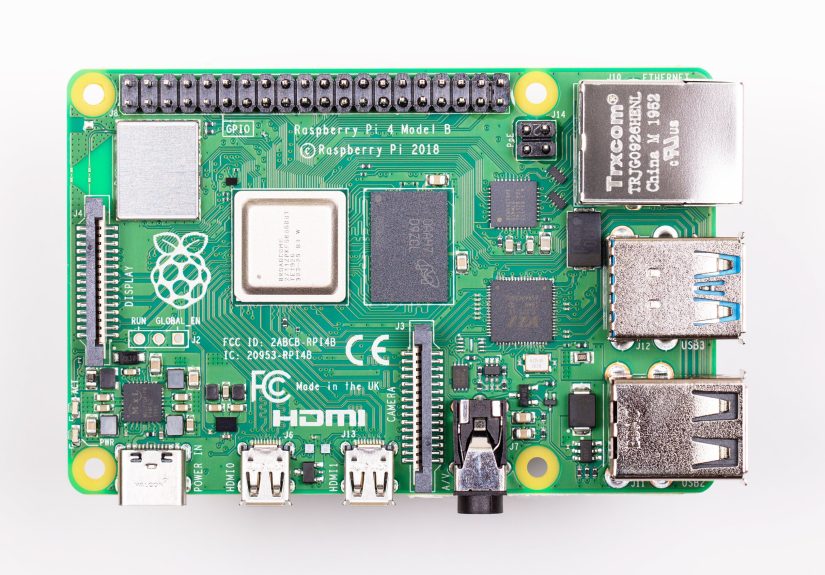
The basic signal path of the board is elegant. An HDMI connector receives video from a source such as a laptop, Raspberry Pi, mini PC, or development board. A receiver chip such as the Texas Instruments TFP401 takes the TMDS-style DVI/HDMI input and outputs parallel RGB pixel data. That parallel data then feeds an RGB-to-LVDS transmitter, which serializes the video into LVDS lanes suitable for the Sony Vaio LCD panel.
In plain English: HDMI comes in, pixel bus comes out, LVDS goes to the panel, and the display hopefully wakes up instead of pretending it has never met you.
This design style is attractive because it can avoid a complex firmware-heavy video scaler. Instead of using a full controller board with menus, scaling, audio handling, and a remote-control receiver nobody asked for, the devboard focuses on one job: converting a compatible input mode into the panel’s native signal format. That makes the board compact and hackable, but it also removes a safety net. If the incoming resolution, pixel clock, timing, or EDID data is wrong, the board will not magically fix it. It is not a video therapist. It is a bridge.
Why The Sony Vaio LCD Makes The Project Interesting
Sony Vaio machines, especially compact models, are popular among hardware hackers because they often used sharp, high-density LCD panels in small form factors. The displays can be excellent candidates for cyberdecks, portable monitors, retro-modern rebuilds, and small workstation projects. The challenge is that laptop panels were never designed to behave like plug-and-play desktop monitors. They expect a specific panel voltage, LVDS lane arrangement, bit mapping, backlight supply, enable signals, and timing.
That means a successful Sony Vaio LCD controller board must be designed around the panel, not around wishful thinking. Before routing a single trace, the designer needs to know whether the panel uses single-channel or dual-channel LVDS, 6-bit or 8-bit color, the required pixel clock range, the connector pinout, the logic voltage, and the backlight arrangement. Guessing here is like seasoning soup with glitter: exciting, memorable, and probably not recommended.
The Main PCB Review Lesson: Rotate The Chip Before You Suffer
One of the most important lessons in this type of PCB review is component orientation. The receiver chip may have HDMI input pins on one side and parallel RGB outputs on another. If the chip is rotated poorly, every trace begins life with a grudge. Differential pairs cross awkwardly, power pins become difficult to feed, and the RGB bus turns into a tiny copper spaghetti festival.
A good PCB layout starts by studying pin groups. HDMI pins should face the HDMI connector as naturally as possible. Parallel RGB pins should face the RGB-to-LVDS transmitter. Power pins should be reachable by short, low-impedance routes with nearby decoupling capacitors. The LVDS transmitter should sit close enough to the panel connector that the LVDS output pairs can be routed cleanly.
If rotating one IC makes twenty traces shorter, two power rails cleaner, and three differential pairs less cursed, rotate the IC. The schematic will not applaud, but the layout will quietly stop screaming.
HDMI Input Layout: Respect The Differential Pairs
HDMI uses high-speed TMDS differential pairs for video data and clock. These pairs should be routed as controlled-impedance differential traces, commonly targeting around 100 ohms differential impedance. On a compact two-layer board, perfect impedance control can be difficult, especially with low-cost fabrication and limited stack-up options. Still, the designer should do the best possible job: keep pairs together, avoid unnecessary vias, avoid stubs, keep return paths continuous, and maintain consistent spacing.
The HDMI connector choice matters more than beginners expect. Through-hole HDMI connectors can be mechanically sturdy, but their staggered signal pins may force awkward routing. Surface-mount HDMI connectors are often easier for clean high-speed routing because the pins are accessible in a more layout-friendly arrangement. There is a trade-off between solderability, durability, cost, sourcing, and signal routing. In a display devboard, where the HDMI input is one of the highest-speed parts of the design, a connector that routes cleanly can be worth more than a connector that merely looks tougher.
HDMI ESD Protection
Any external HDMI connector is an invitation for electrostatic discharge. The user touches a cable, the cable touches the connector, and suddenly your delicate silicon gets introduced to the tiny lightning bolt it never ordered. ESD protection should be placed close to the connector, with short paths to ground and minimal parasitic impact on the TMDS lines. The protection device must be suitable for high-speed HDMI signals; a random TVS diode with too much capacitance can protect the board from ESD while quietly ruining signal integrity. That is not protection. That is sabotage with paperwork.
EDID: The Tiny EEPROM That Makes The Source Behave
EDID, or Extended Display Identification Data, tells the video source what display modes the screen supports. In a normal monitor, the HDMI source reads EDID over the DDC I2C lines and learns the preferred resolution, refresh rate, timing details, and other display information. On a simple HDMI-to-LVDS devboard using a receiver like the TFP401, the board may need a separate EEPROM to provide EDID because the receiver itself is not acting as a full intelligent monitor controller.
This EEPROM is small, cheap, and absolutely important. Without valid EDID, a computer may choose the wrong resolution, refuse to output video, or send a mode the LCD cannot display. For a Sony Vaio panel, the EDID should advertise the panel’s native timing or a known-compatible timing. The DDC pull-ups, EEPROM voltage, write-protect handling, and hot-plug detect behavior should all be reviewed carefully.
Placement is also a design choice. Putting the EDID EEPROM near the HDMI connector can keep the DDC path short. Placing it near a programming header can make updates easier. A neat design often balances both: short enough DDC routing, accessible enough programming, and clear labeling so the future version of you does not need to decode your own PCB like an archaeological artifact.
Parallel RGB: The Wide Bus In The Middle
After HDMI is decoded, the receiver outputs a parallel RGB bus. This may include red, green, and blue data lines, pixel clock, data enable, horizontal sync, vertical sync, and control pins. Compared with HDMI, these traces are not always as intimidating, but they can still create noise, skew, and routing congestion. The pixel clock is especially important because the LVDS transmitter uses it to serialize the data.
The best review approach is to route the RGB bus as a group, keep related signals organized, avoid long detours, and prevent the clock from running through noisy power areas. If the board has room, series damping resistors near the source can be useful for edge-rate control, depending on chip recommendations and measured behavior. Even when they are not populated initially, optional resistor footprints can be a helpful debugging luxury. Future-you loves optional footprints. Future-you also wishes past-you had labeled test pads. Be kind to future-you.
LVDS Output: Small Swings, Big Consequences
LVDS is widely used in laptop panels because it sends high-speed data over differential pairs with relatively low noise and low power. A typical LCD panel may use several LVDS data pairs plus a clock pair. The exact mapping depends on the panel, color depth, and transmitter format. One of the traps in laptop LCD reuse is assuming all LVDS panels share the same pinout. They do not. Some pinouts look similar enough to cause confidence, which is arguably worse than confusion.
The LVDS connector must match the Sony Vaio panel cable or an adapter cable designed for it. Differential pairs should be routed cleanly, with consistent spacing and length awareness. Termination is usually located at the receiver side inside the panel or near the panel input, but the board designer must verify the panel and transmitter requirements. If external termination is required and omitted, the image may fail, flicker, or behave like a haunted spreadsheet.
It is also wise to consider connector placement. Moving the LVDS connector slightly can dramatically simplify routing from the transmitter. PCB design is full of these small mechanical decisions that look cosmetic but secretly determine whether the electrical layout becomes elegant or miserable.
Power Distribution: The Board’s Quiet Dealbreaker
Display boards often need several power domains. The HDMI receiver may require 3.3 V I/O and internal regulated core power. The RGB-to-LVDS transmitter may require clean analog and digital rails. The panel logic may need 3.3 V, while the backlight may require a higher voltage or constant-current LED driver. Even when everything says “3.3 V,” not all 3.3 V pins should be treated as one lazy copper noodle.
A good review checks whether power enters the board cleanly, whether regulators have proper input and output capacitors, whether ferrite beads are placed logically, and whether each IC power pin has a nearby decoupling capacitor with a short return path to ground. Capacitors arranged in pretty groups far away from the pins may look organized, but electrons do not care about your sense of interior design. They care about loop area, impedance, and proximity.
For this kind of board, a 3.3 V plane or generous copper pour can improve distribution. On a two-layer PCB, one side often carries many signals while the other acts as a ground reference. If power traces must be routed manually, they should be wide where possible and neck down only where necessary. Ground stitching vias near decoupling capacitors, connector shields, and high-speed return paths can improve behavior significantly.
Backlight Control: Do Not Just Blast The LEDs
The LCD logic interface and the backlight are separate concerns. A panel can receive perfect LVDS data and still remain dark if the backlight is off. Conversely, a backlight can turn on while the LCD logic is unhappy, giving you a glowing rectangle of disappointment.
Backlight circuits usually need proper enable control, PWM dimming, current regulation, and safe sequencing. Many laptop panels use LED backlights that require more than the logic voltage. A dedicated LED driver is often the right solution because it can regulate current and provide brightness control efficiently. The board should expose or generate signals such as BL_EN and PWM_DIM, and it should ensure the backlight turns on only after panel logic power and valid display signals are stable.
Two-Layer PCB Or Four-Layer PCB?
A two-layer PCB can be cheaper, easier to inspect, and surprisingly capable when designed carefully. For a hobby devboard, it may be perfectly reasonable. However, HDMI and LVDS both benefit from good return paths and predictable impedance. A four-layer PCB with solid ground and power planes makes controlled routing easier and reduces electromagnetic drama. It also gives the designer more freedom to route power without carving up the return path under high-speed signals.
The decision depends on project goals. If the board is a personal prototype for a Sony Vaio rebuild, two layers may be acceptable with careful routing and realistic expectations. If the board is intended for repeatable production, compliance testing, or reliable operation across many sources and cables, four layers become much more attractive. Cheap prototypes are wonderful, but debugging marginal HDMI behavior at 2 a.m. has a way of making four-layer boards look like a bargain.
Connector And Mechanical Review
Connector footprints deserve serious attention. HDMI receptacles come in many mechanical variants, and the footprint must match the exact part. LCD connectors are even more dangerous because fine-pitch FFC/FPC parts can have top-contact or bottom-contact versions, different locking styles, different pin numbering, and similar-looking packages that are absolutely not interchangeable.
A good PCB review should include a printed 1:1 footprint check. Place the actual connector on the printout. Verify pin 1. Confirm cable exit direction. Check whether the enclosure, panel cable, and HDMI cable can physically coexist. Many boards fail not because the schematic was wrong, but because the cable needed to bend through a screw post, a battery, and the designer’s optimism.
Bring-Up Plan: How To Test Without Panic
Bring-up should be staged. First, power the board without the panel connected and verify regulator outputs. Check 3.3 V rails, current draw, and whether any IC gets hot enough to make you reconsider your hobbies. Next, confirm EDID can be read over HDMI DDC. Then check the receiver output clock with a scope or logic analyzer if available. After that, connect the LVDS panel and test with a known compatible video mode.
Test pads are cheap insurance. Add pads for 5 V input, 3.3 V, ground, HPD, SCL, SDA, pixel clock, panel enable, backlight enable, and PWM. If the board supports EDID programming, label that header clearly. If jumpers select panel voltage or backlight behavior, make their default state obvious. Debugging a dense board without test points is like trying to fix a watch through a keyhole while someone keeps turning off the lights.
Common PCB Review Mistakes To Avoid
Routing Before Floorplanning
The fastest route to a messy board is to start routing before deciding where each functional block belongs. Place HDMI input, receiver, RGB-to-LVDS transmitter, panel connector, regulators, EEPROM, and test headers with signal flow in mind. Good floorplanning reduces the need for heroic routing.
Ignoring The Return Path
High-speed signals do not travel alone. They travel with return currents. If the ground reference under a differential pair is broken by slots, cuts, or unrelated traces, signal quality can suffer. Keep ground continuous under HDMI and LVDS routes whenever possible.
Using Pretty Decoupling Instead Of Effective Decoupling
Decoupling capacitors should be close to the power pins they support. A symmetrical capacitor garden in the corner of the board may look tidy, but it will not help a noisy IC pin located across the neighborhood.
Forgetting Manufacturing Reality
Fine-pitch connectors, QFP packages, and dense routing are manageable, but only if the chosen PCB manufacturer can reliably produce the trace width, spacing, drill sizes, and solder mask features. Design rules should be set before routing, not after the board has become a copper maze.
Experience Notes From HDMI To LVDS LCD Devboard Projects
One practical lesson from display-adapter projects is that the first prototype is rarely just a prototype; it is a teacher with invoices. The board may power on, the EDID may read, and the HDMI source may detect a display, yet the panel remains black because one tiny assumption was wrong. Maybe the LVDS bit order does not match the panel. Maybe the backlight enable polarity is inverted. Maybe the source selected a refresh rate the panel dislikes. This is why successful designers leave themselves options: solder jumpers, test pads, alternate resistor footprints, and enough silkscreen notes to make the board understandable six months later.
Another experience-based recommendation is to separate “must work” from “nice to have.” The must-work list includes stable power, correct HDMI routing, readable EDID, valid pixel clock, correct LVDS mapping, proper panel voltage, and safe backlight control. Nice-to-have features include buttons, brightness presets, decorative logos, extra headers, and fancy mounting slots. There is nothing wrong with nice features, but they should not steal layout quality from the critical path. A devboard with a cute mascot and broken HDMI is still a broken devboard, just with better branding.
When reviewing a board like this, it helps to imagine the signal as water flowing through pipes. HDMI enters as a fast, narrow, pressure-sensitive stream. The receiver turns it into a wide parallel river. The LVDS transmitter compresses it back into controlled high-speed lanes. Power rails are the pumps. Ground is the plumbing foundation. Connectors are the fittings. If one fitting points the wrong way, everything becomes harder. That is exactly why chip rotation and connector selection matter so much. A single 90-degree component decision can create hours of unnecessary routing pain.
It is also worth testing with multiple HDMI sources. Some computers are forgiving. Others behave like royalty inspecting table manners. A Raspberry Pi, a Windows laptop, a mini PC, and a USB-C dock may each handle EDID and output timing differently. If the board works with one source but not another, the issue may be EDID content, hot-plug timing, signal integrity, or unsupported video modes. Good documentation of tested sources can save users from blaming the wrong part of the system.
Finally, do not underestimate thermal and mechanical behavior. A board installed inside a compact Sony Vaio-style rebuild may sit near batteries, regulators, plastic shells, and limited airflow. Linear regulators are simple but can waste heat. LED backlight drivers can generate switching noise and warmth. HDMI cables can apply mechanical stress. FPC cables can loosen if the board flexes. A polished devboard is not only electrically correct; it is physically survivable. The best design is the one that still works after being assembled, moved, opened, closed, and handled by a human who insists they are being careful.
Conclusion
The PCB Design Review: HDMI To LVDS Sony Vaio LCD Devboard topic is a perfect reminder that display hardware rewards patience. The concept is simple: receive HDMI, decode it to RGB, transmit LVDS, and light up a beautiful Sony Vaio LCD. The design work is more nuanced: choose the right connector, rotate chips intelligently, preserve differential-pair quality, provide correct EDID, route power with intention, place decoupling capacitors close to pins, and treat the backlight as a real subsystem rather than an afterthought.
For makers, hardware hackers, and embedded display designers, this kind of board is both challenging and deeply satisfying. It turns a salvaged laptop panel into a useful display and turns a PCB layout into a lesson in signal integrity, power integrity, and mechanical common sense. When it works, the reward is not just a screen lighting up. It is the quiet joy of knowing that the copper maze you designed is no longer a maze. It is a road.